I created an account on Circuit Lab and designed my 1st circuit. Actually, I really designed it on a sheet of paper and after editing, and editing, and editing... I decided to look for an online way of designing a circuit - I Googled circuit design and Circuit Lab popped up - I created an account and started. It seems pretty simple, which is exactly what I'm looking for right now.
Here is the schematic of my 1st design:
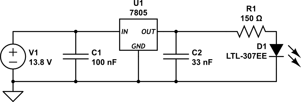
I needed a circuit that would take a 12 - 14vDC source and transform it to 5vDC. I'm planning on using a Garmin 18x LVC, which needs about 100mA @ 5vDC. Since I had most of the components already figured out, I thought that I'd add an LED - you know, just for fun! So, I did :)
Here's my breadboard pic:

73 de KJ4WLH